Features:
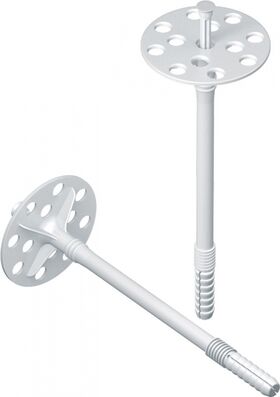
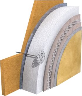
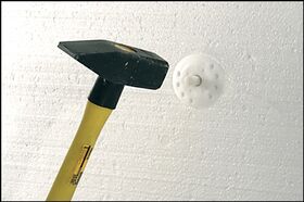
Hammer insulation fixing with a plastic pin designed for embedding of Jointless Facade Thermal Insulation Systems.
Product features:
- Product is recommended for installation of facade thermal insulation in concrete and solid brick (ETA) substrate;
- Lowest embedment depth with maximum high performance parameters;
- Shortest drilling depth – saves installation time;
- Optimal technical parameters for detachment to ensure the safety of the product;
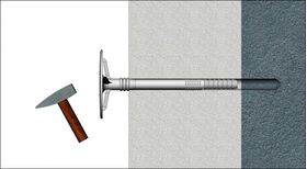
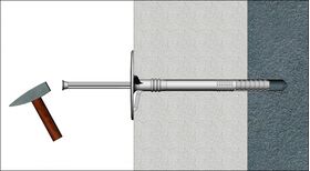
- Polyamide pin design reinforced with glass fibre – allows fast and trouble-free installation in the expandable section of the expansion plug;
- Optimal reduction of thermal bridge through the use of an additional plastic pin;
- The possibility of using a fixing with an extra KWL insulation holding flange (recommended in the use of mineral-lamella wool);
- Economical consumption through optimal product parameters
Material:
- Plug Sleeve: impact resistant copolymer of polypropylene PP.
- Nail Pin: polyamide PA 6.0 (Nylon) reinforced with fibre glass.
Installation recommendations:
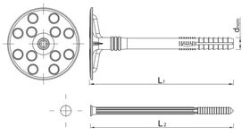
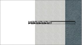
- drill diameter: 10 mm,
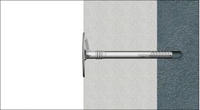
- minimum embedment depth: ETA 25mm
Dedicated substrates
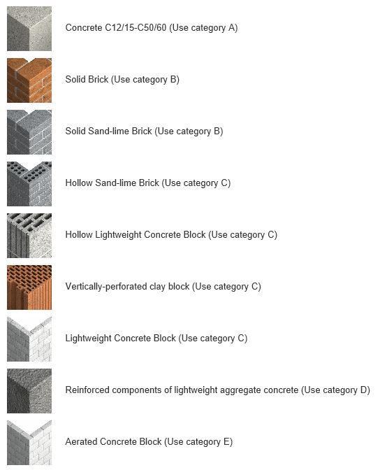
Application
| Lenght [mm] |
Max. insulation thickness [mm] |
Package [pcs] |
| 70mm | 40mm | 250 Stk |
| 90mm | 60mm | 250 Stk |
| 120mm | 90mm | 250 Stk |
| 140mm | 110mm | 250 Stk |
| 160mm | 130mm | 250 Stk |
| 180mm | 150mm | 250 Stk |
| 200mm | 170mm | 250 Stk |
| 220mm | 190mm | 250 Stk |
Performance data for single anchor in tension without influence of edge distance and spacing
| Substrate | Concrete min. C16/20 | Concrete C12/15 | Solid brick | Sand-lime solid brick | Perforated ceramic brick | Perforated ceramic brick (i.e. Porotherm) | MEGA MAX | Sand-lime hollow brick | Lightweight concrete solid block | Lightweight concrete hollow block | Aerated concrete | |
| Embedment depth hef | [mm] | 25 | 25 | 25 | 25 | 40 | 40 | 40 | 25 | 60 | 40 | 60 |
| MEAN ULTIMATE LOAD NRu,m | ||||||||||||
| KI-10 | [kN] | 0.70 | 0.78 | 0.72 | 0.89 | 0.74 | 0.57 | 0.67 | 0.96 | 0.78 | 0.75 | 0.25 |
| CHARACTERISTIC LOAD NRk | ||||||||||||
| KI-10 | [kN] | 0.50 | 0.50 | 0.50 | 0.60 | 0.40 | 0.40 | 0.30 | 0.60 | 0.50 | 0.40 | 0.10 |
| DESIGN LOAD NRd | ||||||||||||
| KI-10 | [kN] | 0.25 | 0.25 | 0.25 | 0.30 | 0.20 | 0.20 | 0.15 | 0.30 | 0.25 | 0.20 | 0.05 |
| RECOMMENDED LOAD Nrec | ||||||||||||
| KI-10 | [kN] | 0.18 | 0.18 | 0.18 | 0.21 | 0.14 | 0.14 | 0.11 | 0.21 | 0.18 | 0.14 | 0.04 |
| Fixing type | KI-10 | |
| Plate resistance | [kN] | 0.86 |
| Plate stiffness | [kN/mm] | 0.50 |
| Point thermal transmittance χ | [W/K] | 0.00 |
No posts found


